Figure 1: Installed system
Considerations for reusing existing distribution systems when upgrading equipment
The Glitch:
An installer is asked to replace two aging cast-iron boilers with two mod/con boilers, but reuse as much of the existing distribution system as possible. The system’s owner is also complaining about “sloshing” sounds coming from some of the zone circulators. Since the distribution system is several years old the installer decides to include a Y-strainer to capture dirt particles before they can enter the compact heat exchangers on the new boilers. The system that gets installed is shown in Figure 1 (above). Can you spot several details, omissions or other quirks that will lead to problems over the life of this system?
The Problems
- The boiler circulators are, in effect, in series with the zone circulators. When either boiler circulator is on, it will create sufficient pressure differential across the distribution headers to push flow into zones that are supposed to be off;
- There are no check valves in the boiler circuits. When either boiler circulator is on, there will be some reverse flow through the other boiler;
- There are no valves that allow each boiler to be isolated for service, if necessary;
- There are no valves to isolate the Y-strainer, which is necessary when removing its internal screen for cleaning;
- The pressure-reducing valve should be downstream of the backflow preventer;
- There should be at least 10 pipe diameters of straight pipe upstream of all circulators, and upstream of all check valves. This dampens turbulence which could cause the circulators to emit noise or go into cavitation. The internal assemblies in some check valves can also rattle if the entering flow is highly turbulent;
- There are no purging valves on the return side of each zone circuit;
- One check valve is missing on the far right zone circuit; and
- There is no way to isolate the expansion tank if it has to be removed.
One Fix
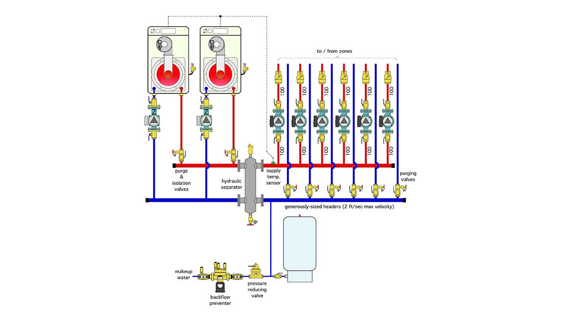
The system shown in Figure 2 corrects the deficiencies described above.
FIGURE 2

This system uses a hydraulic separator for several functions. It eliminates interaction between the boiler circulators and the distribution circulators. It provides high-efficiency microbubble air separation for the system. It replaces the function of the Y-strainer while creating lower head loss, eliminating the need for isolation valves.
The boiler circulators are now equipped with check valves. Purging valves have been added to enable boiler isolation and drainage if necessary. Purge valves have also been added to the return side of each zone circuit. Straight lengths of pipe have been used upstream of the zone circulators and check valves to reduce turbulence and the noise associated with it. The backflow preventer is now upstream of the pressure-reducing valve. An isolation valve has been added to the pipe connecting to the expansion tank.
The headers in the system are generously sized so that the maximum flow velocity with all zone circulators operating doesn’t exceed 2 feet per second.
Also, note that the supply temperature sensor for the boilers is located downstream of the hydraulic separator. In that location, it measures the true supply temperature to the zone circuits, which will often differ from the boiler outlet temperature due to mixing within the hydraulic separator.
Another possibility
Although the budget constraints imposed by the owner might prevent replacing the zone circulators, the long-term operating cost of this system would definitely be lowered by replacing those six older circulators with a single variable-speed pressure-regulated circulator, combined with zone valves. This option is shown in Figure 3.
FIGURE 3

The variable speed circulator would operate in constant differential pressure. Its speed would automatically ramp up and down depending on the number of active zone circuits.
The hydraulic separator now includes a magnet to capture iron oxide particles. This type of separator is recommended whenever modern circulators with permanent magnet (ECM) motors are used.
Balancing valves have also been added to each zone circuit so the individual zone flows can be established and maintained. The balancing valves are positioned so that they can be closed, along with the zone’s purging valve and the circulator isolation valve to isolate a zone valve if it has to be opened for service.